A recent boiler retrofit project highlighted the incredible benefits of the press fitting process while illustrating some of the potential concerns that might arise while using this system.
We received a last minute request from a homeowner (in the middle of winter!) to replace two existing non-condensing boilers with two new Viessmann condensing boilers. As we were in the middle of the heating season there wasn’t a lot of time to consider different approaches to this situation—this became a moot point as the homeowner insisted on using the Viessmann boilers that his engineer had specified.
Nelson Mechanical Design
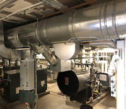
Old boilers and breeching in the mechanical room.
The existing boilers were nearing the end of their service life and their connection to the existing heating loop didn’t make much sense—all loop water flowed directly through the boilers even when they were inactive. So we scrambled to design and install a boiler system that would successfully integrate the new Viessmann boilers with the existing heating loop within the existing space.
A significant part of the success of any retrofit project is to understand the constraints that will end up driving the design and choice of materials and joining methods. We knew that we had to use press fittings due to the time constraint; boiler venting would end up dictating boiler height and spacing; the available height would drive the choice of piping and connections; and creating a strut jig for the piping and press fittings would be critical to make the installation presentable and able to fit within our space constraints.
Nelson Mechanical Design
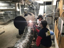
Cutting up the old boiler for removal.
Demo of Old Boilers
We drained the heating loop and demo-ed the existing non-condensing boilers. We had to cut out the old propane gas lines and heating supply and return lines; we ended up cutting the boilers apart on-site and removing smaller chunks of boiler through the finished basement space. With a blank slate we could now consider how to make the two Viessmann boilers fit into our available space.
Boiler Choice Drives our Space Constraints
Because the boilers had been specified for this project, we had to work within their dimensional and technical constraints. This led to an interesting cascade of decisions that ultimately dictated the design and installation of the entire project.
The existing boilers had steel smoke pipe breeching into a masonry chimney up through the center of the house. Because the two new boilers were condensing, we had to line the chimney with PPE flexible boiler vent piping. We struggled for a bit (we discovered that there was an undocumented jog in the chimney flue) and finally installed the two 50 foot flexes and connected them to their special transition fittings at the base of the chimney.
Nelson Mechanical Design
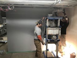
Mounting the right boiler based on vent height.
These fittings would now give us our vent height and be used to make the transition to rigid PPE vent pipe for each of the two boilers. With this vent height we were able to work backwards to figure out the maximum height of the two boilers. The first venting elbow dictated the right boiler location and the piping between the boilers dictated the left boiler location.
New Boiler Wall for two Viessmann boilers
With this information we were able to frame up a wall faced with plywood upon which we would install the two new Viessmann condensing boilers. The length of this wall was determined by the size of the mechanical room that had enough height for the two boilers as the other mechanical spaces were too low. We now had our blank slate with which to design and assemble the piping that would connect the two boilers to the existing heating loop.
Time Constraint and Press Considerations
We had arrived at a design for the two new boilers based on the venting height constraints and the boiler height requirements as dictated by the bottom supply and return connections on each boiler.
Nelson Mechanical Design
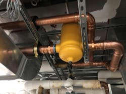
New air separator pressed in with strut cushion clamps for support and location.
Now we had to address the time constraint—if we could press this system together it would greatly speed up this project. Based on the size of the piping (copper tube ranging from 1-1/4” to 3”) it would be possible to solder all of the fittings but it would be quite challenging.(Full disclosure—I only have soldered connections in my hydronic system at home with copper tubing ranging from ¼” to 2”—I almost never have leaks in the smaller sizes but have been known to have a few leaks in 1-1/2” and 2” joints.)
We had a fixed amount of space between the two boilers so we mocked up both copper press fittings and sweat fittings and confirmed that both would work within the given space. At this point, going with press seemed to be a no-brainer; if we went with press we would have the boilers up and running in a fraction of the time it would take to solder all of the fittings… but what were the pros and cons of our situation?
Nelson Mechcanical Design
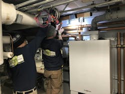
Pressing large fittings in the correct order to avoid getting pressed into a corner.
Advantages of the Press System
The Press system had tremendous advantages.
Techs that didn’t have solder skills could be successful installing press fittings, soldering large fittings was inherently challenging, there was no need to completely drain any pipes, press was very fast and rarely leaked, and press could be used for gas fitting too!
We ended up using Viega Mega Press fittings to do the gas piping for the two boilers. The existing black malleable iron piping was 1-1/4” for the main and each boiler was served with 1” pipe. We cut and pressed that in a fraction of the time it would have taken to cut and thread all of those pipes and nipples. Much cleaner too, with no cutting oil mess.
Nelson Mechanical Design
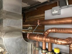
Loop supply and return piping installed to permit pressing.
Drawbacks of the Press System
The Press system did have some notable drawbacks.
Techs needed to anticipate treachery from the press process; there was no going back after it was pressed, and betrayal seemed to lurk with every press of the button. If the piping assembly was not successfully constrained then a plumb, level, and square piping assembly was seldom possible. Press fittings were more expensive than solder fittings, they couldn’t be reused, and you couldn’t heat up and realign a pipe or fitting to make it perfectly plumb or level.
Because the way in which an assembly would shift or move when pressed was inherently unpredictable, techs in the field could perceive that it wasn’t possible to make their work plumb or level or beautiful.
Nelson Mechanical Design
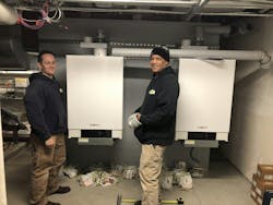
Left and right boilers mounted.
With press you had to be absolutely confident that the press tool would be able to get to each fitting to press it—which meant that now there was a critical sequence of which fittings to press and in what order so that you didn’t press yourself into a corner! Ha!
If you pressed the fittings in the wrong order you might end up with a fitting that you couldn’t reach with the press tool, and that would mean cutting out some of your work to get to that inaccessible fitting.
With soldering you could establish the highest standards of perfection in terms of plumb, level, and square and techs could build their skills with heat control and layout over many years of practice to arrive at mastery.
Press, to have same high standards of perfection as soldering, would require complete support and constraint of all fittings and pipe in all directions.
Strut to the Rescue – the speed of Press but still Plumb, Level, and Square
Nelson Mechanical Design
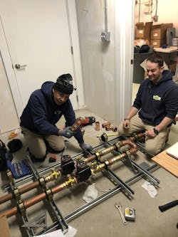
Strut framework anchored to the floor for assembly of boiler piping.
Our approach with our techs was simple: press was here to stay and few jobs moving forward (besides repairs) would be soldered. They could still achieve mastery and be capable of plumb, level, and square piping projects, but they would need to learn how to control and constrain the movement of the pipes and fittings during the Press process.
Our approach was to set up a framework of strut to which they could clamp their piping assemblies—this gave them the ability to constrain the piping. For this project, we set up a strut frame on the concrete floor—we then used cushion clamps to hold the piping perfectly square and level so that nothing could move during the press process.
How and where to install the cushion clamps was dictated by the experience gained from previous press betrayals. It would take more time to install additional cushion clamps, but that avoided a crooked assembly after pressing.
Nelson Mechanical Design
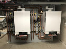
Boiler piping almost done.
Press Makes the Project Possible
With all of our thinking and layout done, we were able to build the strut framework, press up our boiler piping subassemblies, connect them to the two boilers, connect the two boilers to the existing loop via closely spaced tees, and press up the gas piping in a fraction of the time it would have taken with soldering and cutting and threading pipe. We filled up the system and fired up the boilers and got the heat back on. No leaks and the boilers ran well.
>>> Read full article>>>
Copyright for syndicated content belongs to the linked Source : ContractorMag – https://www.contractormag.com/hydronics/article/55038593/tricky-hydronic-install-press-systems-can-make-it-possible


